E-Z Frames
Patent #4,993,877
 We proudly introduce our newest product...
Consider the advantages:
Cost Savings
- Labor costs drastically reduced.
- Less forming material less cost.
Simple Installation
- Personnel inexperienced in forming can easily install.
- Frames attach simply without the use of wire, nails and seat forms.
- Quickly adjusts for leveling.
- Frames easily cut in the field.
- Frames easily welded in the field.
A Superior Frame Design That Produces Quality Trench Installation
- Insures level frame installation.
- Provides superior anchorage in concrete.
- Reduces risk of spalling of concrete underframes.
- Continuous bearing surface with fewer joints.
- Supplied in standard 4'0'' lengths.
- Excellent with brick pavers and tile.
![]()
![]()
E-Z Frame Installation & General Trench Forming Procedures
(One Suggested Method)
Advantages of your new E-Z Frame
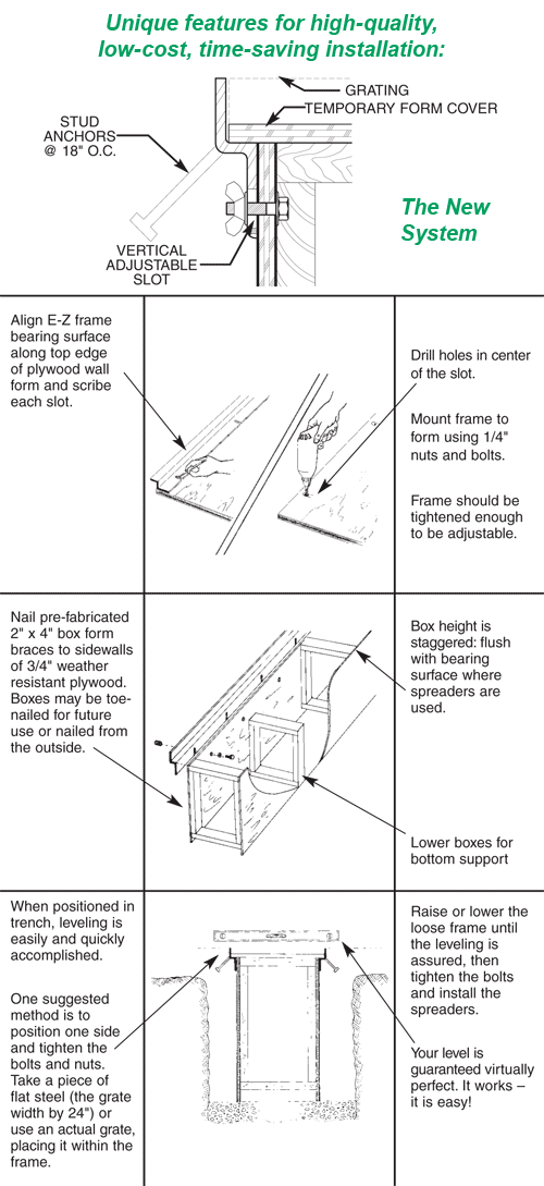
 The development of the E-Z Frame has revolutionized the age-old method of trench forming with short conventional cast frames. The most common, current method of trench forming - using conventional 24 to 36 inch cast frames - is a time-consuming and difficult procedure resulting in higher costs with less than satisfactory results. Frame attachment and leveling problems become practically non-existent through the use of E-Z Frames. Your E-Z Frames are easily positioned and tested for proper grade and spacing prior to the pouring of concrete.
![]()
![]()
Material needed for E-Z Frame installation
Trench Form Sidewalls: Good grade weather-resistant plywood (3/4 inch or greater as required).
Sidewall Bracings : 2" x 4" lumber or other suitable bracing material for bracing studs.
Hardware:
- 1/4" x 1- 1½" bolts (or longer if plywood exceeds 3/4" thick the bolt should not be excessive in length. An excessively long bolt will be difficult to remove after the concrete has cured).
- Wing nuts and washers.
- Nails
Grate & Spacing Material: Grates or flat rigid pieces of material same width and length as the grate covers.
Leveling Tool: Carpentry level.
General Tools & Proper Safety Equipment
General Note
The following is offered as a general guideline to E-Z Frame installation and trench forming procedures. In no way is the following to be construed as complete and detailed instructions for frame installation and trench forming procedures. In all installation and forming procedures used, good construction practices should be followed to insure a safe working environment.
Installation Procedures After the trench bottom concrete slab has been poured to the specifications and cured, a trench form must be built. (It is recommended that the floor slab be reinforced with re-bars or wire mesh. The slab can also be keyed for the vertical concrete wall in accordance with good construction practice).
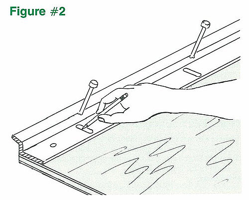
1. To construct one trench form unit, cut two pieces of plywood to the same proper dimensions desired to match the trench bottom slab and the slope of the finished grade of trench. The height of the plywood should come below the finished grade by the thickness of the edge of the grate plus 1/2 inch to allow for up or down frame adjustment. See figure #1. (Example: Trench bottom concrete slab to desired finished concrete surface = 23 inches. Grate bearing edge thickness = 1 - 1½". 23 inches - 2 inches (1 - 1½" + 1/2") = 21 inches. The plywood should be cut to 21 inches at this point).
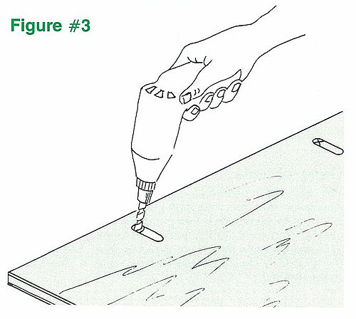
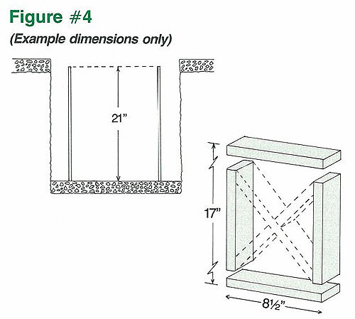
3. Remove the E-Z Frame and drill 5/16" diameter holes, into both pieces of the plywood, corresponding to the top of the scribed slot. See figure #3. At this point, for those skilled in the assembly of trench forms and desiring B. Construction of the sidewall bracings 1. The sidewall braces are constructed with 2" x 4" lumber or other suitable bracing materials. (An alternate material could be plywood, 3/4 inch thick or greater as needed). To determine the proper bracing dimensions, take the width of the desired trench clear opening minus twice the thickness of the plywood used. This will give you the proper overall width of the form bracing needed). (Example: Desired trench clear opening is 10 inches. The trench form sidewalls's thickness (the plywood) you are using is 3/4 inch thick. 3/4 inch x 2 = 1-1½ inches. Therefore, 10 inches minus 1-1½ inches = 8-1/2 inches. 8-1/2 inches is the overall width to which each of the form bracings should be constructed).
2. Build the appropriate number of sidewall braces. The number of sidewall braces to be built is a function of your site conditions and the amount of concrete pressure to be exerted on your trench form. You should build enough sidewall braces necessary to provide a safe working environment. (For large trenches, X bracing may be desired as shown by dotted lines in figure #4.) C. Positioning of the sidewall braces to the trench form sidewalls (the plywood)
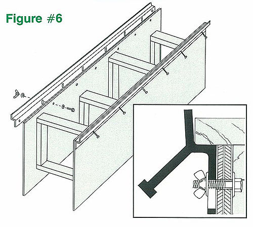
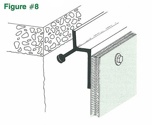
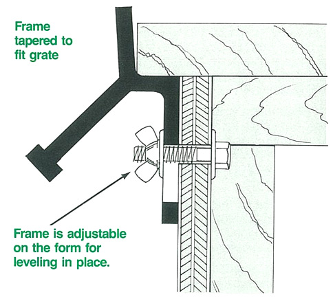
2. At this point, additional trench form units may be constructed to form the desired trench length. Repeat steps A through C for each additional trench form unit required. D. Attachment of the E-Z Frame to the trench form sidewalls 1. On all of your constructed trench form units, simply attach the E-Z Frame to the side of the plywood trench form that will be embedded into concrete, using the 1/4 inch x 1-1½ (or longer) bolts, wing nuts and washers.(The wing nut should be outside of the plywood. This allows the wing nut to be locked in the cured concrete for easy bolt removal). The frame should be mounted in the top of the slot.
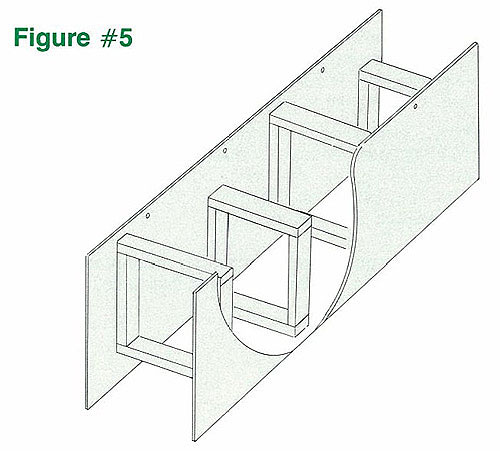
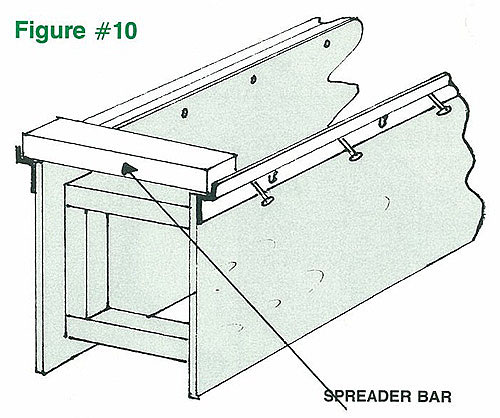
E. Placing and positioning the trench form units into the excavated trench 1. Place the trench form units into the excavated trench, sitting on the poured concrete slab. Position each form unit for proper trench alignment. 2. Sidewall braces should be positioned and nailed to overlap all the joints of each trench form sidewall units. This helps to ensure a tight joint and proper alignment from one trench form unit to the next. See figure #7.
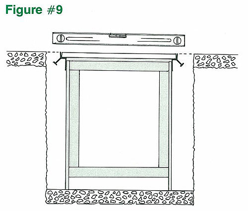
F. Positioning and testing the E-Z Frame's proper grade (prior to concrete pouring)
2. Place one of the grates to be used - or a flat rigid piece of material the same length and width of the grate - on the properly positioned E-Z Frame and on the opposite un-positioned E-Z Frame's seat. 3. Adjust the unpositioned frame to the same plane as that of the opposing frame (which is properly positioned). This is achieved by sliding the unpositioned frame up or down on the bolt through the slot, with the grate or flat piece of material remaining on the frame until it no longer rocks.
5. Tighten all wing nuts and bolts to firmly secure the frames against the form walls. 6. At this point, a nail or a screw may be inserted and driven into the plywood through the holes found at each end of the E-Z Frame. This helps to insure that the frames do not shift out of position while attached to the trench form before and during concrete pouring. G. Testing the E-Z Frame for proper spacing (prior to concrete pouring) 1. In order to verify the E-Z Frames are properly spaced for the grates / covers to fit, simply place a grate / cover or a flat piece of rigid material the same size and width of the grate / cover on the E-Z Frame seating surface at each end of the trench form unit. One grate should overlap joining ends of each form unit to ensure proper form alignment. Also, verify the angular space (the amount of space between the frame and the edge of the grate / cover). When the grate / cover is pushed snugly against one frame, there should be 3/16" to 1/4" space between the grate / cover and the opposing frame.
3. Concrete can now be poured outside the trench form units. Caution and good forming procedures should be used during the pouring process. The pour should be on alternating sides of the trench form units to help prevent shifting. 4. After the concrete has cured, remove the trench forms. We recommend that you remove any debris that may have gotten onto the frames during the trench forming process. Your frames are now ready for grate/cover installation and your trench installation is complete! If you have any questions concerning the installation of E-Z Frames, |